Quzhou Aoyin Metal Materials Co.,Ltd


Battery Box Wall Thickness: How Thin Is Too Thin
Blog
Battery Box Wall Thickness: How Thin Is Too Thin
Release time:
2026-10-09
Source


Why thin walls fail in ways thicker ones never do
A box that is too thin almost never fails in the factory. It fails in the sixth month, on the road. The enclosure passes incoming inspection, passes its leak test, and carries the pack without complaint through assembly. Then a season of washboard roads and standing water does its work: the lid bows between its mounting bolts until the gasket lifts on one side, water tracks in along the seam, and the failure gets filed under "seal quality" — when the dimension that caused it was the wall.
Thin walls rarely break. They deflect — and deflection at a sealing face looks exactly like a bad gasket.
Wall thickness is a stiffness lever, not a strength one
Specifying wall thickness is a stiffness decision, and strength barely enters into it. Tensile strength belongs to the alloy and the temper: a 1.2 mm wall of 6063-T6 and a 3.0 mm wall of 6063-T6 carry the same minimum rating. What differs is how far the wall moves under a load nowhere near breaking it.
Strength answers "will it tear"; stiffness answers "will it bend out of the way". A pack sitting on the floor of an e-rickshaw box stresses that wall to a few percent of its yield — what it does instead is sag, and the sag opens the seal. So the alloy decision in 6063 vs 6061 vs 6082 and the wall decision are separate, and picking the stronger alloy does not buy a thinner wall.
Stiffness falls with the cube of wall thickness
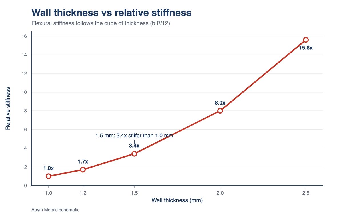
Halve the wall and the enclosure becomes eight times more flexible, not two times. Flexural stiffness follows the cube of thickness: for a wall of width b and thickness t, the second moment of area is b·t³/12. The thickness term is cubed; everything else stays linear.
| Wall thickness | Relative stiffness | Deflection under the same load | Practical meaning |
|---|---|---|---|
| 1.0 mm | 1.0 | 1.00 (baseline) | Bows visibly between supports; sealing faces need reinforcement |
| 1.2 mm | 1.7 | 0.58 | Floor for extruded box walls; needs short support spacing |
| 1.5 mm | 3.4 | 0.30 | Usual battery-box wall; holds a gasket face without stiffening |
| 2.0 mm | 8.0 | 0.13 | Stiff enough for long spans and bolted load paths |
| 2.5 mm | 15.6 | 0.06 | Stiffness stops being the constraint; weight and cost are |
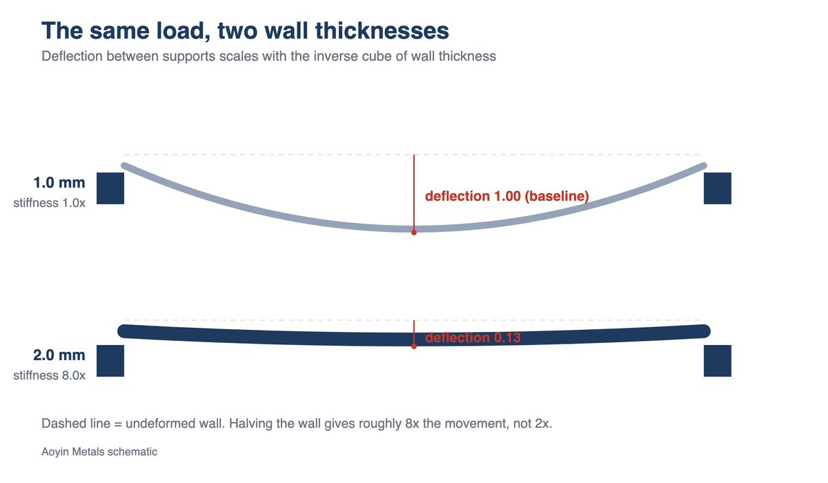
Read the table in the direction that matters: going from 1.5 mm to 1.2 mm — a 20% saving on paper — leaves the wall with half the stiffness, so the same load deflects it nearly twice as far. Published work on optimizing extruded structures treats wall thickness as a variable with a hard manufacturing floor, which is the right way to hold it.
What the extrusion press allows
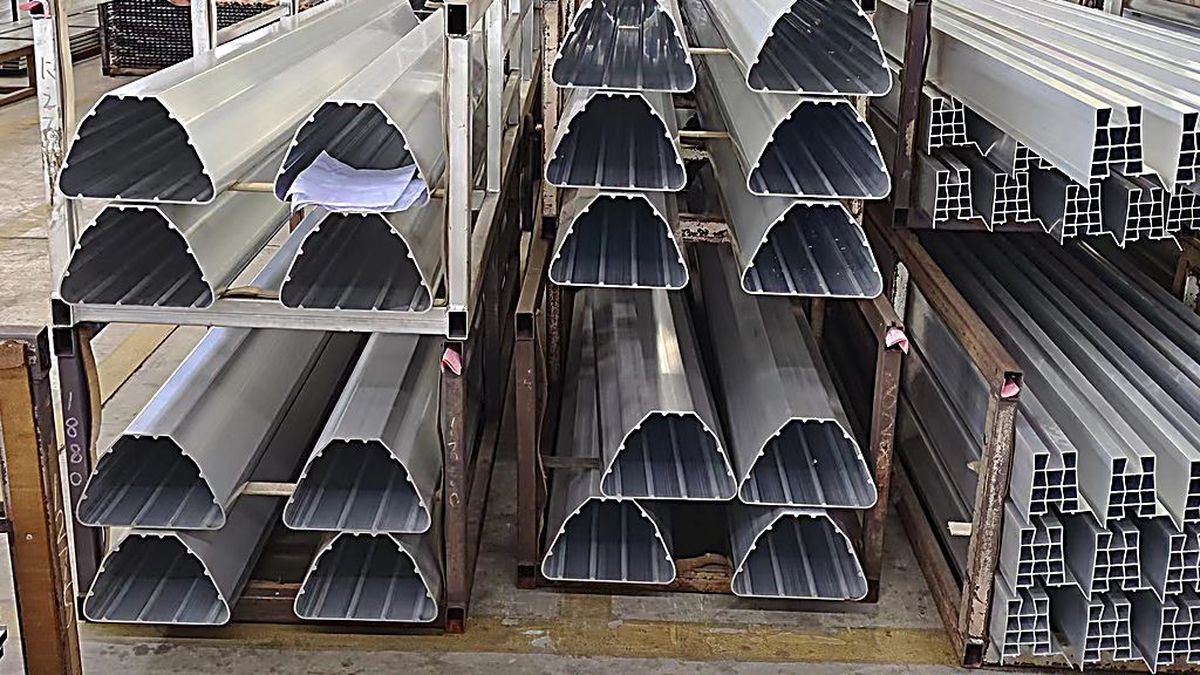
Extrusion, not strength, sets the floor: below roughly 1.2 mm, a battery box profile stops filling consistently. Metal has to flow through a die aperture that narrows with the wall, and a press that fills 2.0 mm easily will starve 0.8 mm at the far end of the section.
| Variable | Where the limit sits | Practical meaning |
|---|---|---|
| Minimum wall | ≥1.2 mm for extruded box walls | Below this, fill becomes inconsistent and scrap climbs |
| Extrusion ratio | 6063 ≈ 15–30; 6061 ≈ 10–25 | 6061 is stronger but flows less, so it needs thicker walls |
| Section balance | keep thick-to-thin near 2:1 | Unbalanced sections leave the press with built-in stress |
| Circumscribing circle vs thinnest wall | practical ceiling near CCD/t_min ≈ 138 | Past this ratio, thin features stop filling reliably |
| Corner radii | inside R ≥ 2 mm; outside R ≥ 1 mm | Sharp corners starve the die and concentrate stress |
The extrusion ratio is why switching to 6061 for strength quietly forces the walls thicker: the section that filled in 6063 may not fill in 6061 at all. And the CCD/t_min limit is why a large envelope with a thin wall is harder than a small one with the same wall. Both mechanics are set out in how aluminum extrusion works and in the materials hub.
Where wall thickness meets the tolerance band
The thinner the wall, the larger the share of it that the tolerance band consumes. Per GB/T 6892, a 2.0 mm wall carries ±0.25 mm in the general class and ±0.15 mm in the precision class. Take the precision band: the same ±0.15 mm is 7.5% of a 2.0 mm wall and 12.5% of a 1.2 mm one — and it is the thin wall, with the least stiffness margin, that takes the bigger hit.
Strength is quoted by thickness band the same way. Per EN 755-2, in the band up to 10 mm: 6063-T6 carries minimums of 215 MPa tensile and 170 MPa proof stress, 6061-T6 reaches 260 and 240, 6082-T6 reaches 310 and 260. Those are minima for the temper, not typical values for one thickness — a mill certificate per heat belongs in the file. Finishing takes metal too: a Type II film consumes about two thirds of its thickness from the substrate, so 15 µm removes roughly 10 µm of wall per face, as explained in what anodizing does to a battery box. Both numbers belong on the drawing, alongside the tolerance basis in the 8 things to fix before the drawing.
Why thin walls corrode through first
Corrosion removes depth, not proportion, so the thinner the wall the sooner a pit becomes a hole. A given environment attacks aluminium at roughly a fixed penetration per year; what differs between 1.2 mm and 2.0 mm is how much metal sits behind the pit.
| Root cause | What it looks like in the field | The number that matters |
|---|---|---|
| Deflection at the seal | intermittent water ingress, no visible defect | 1.2 mm deflects about 1.9× more than 1.5 mm under the same load |
| Thread pull-out | bolt spins, boss cracks | an M4 thread in a 1.2 mm wall engages barely two pitches |
| Corrosion margin | pinholes after two monsoon seasons | a 0.3 mm pit is 25% of a 1.2 mm wall, 15% of a 2.0 mm one |
| Machining chatter | wavy sealing face, uneven gasket squeeze | thin walls deflect away from the cutter instead of being cut |
The thread case surprises people, because it is not a material problem. Below about two pitches of engagement the joint fails by stripping, and no alloy change fixes it — the fix is a boss, a thicker mounting rail, or an insert, and it costs far less than thickening the whole section.
Where thin walls reach their limit
Thin walls are correct when nothing loads them in bending, and wrong wherever a bolt, a long span or a wet decade does. Three cases each way:
Light, short spans — small panels and covers carrying no load are where 1.2–1.5 mm earns its saving. Published optimization work reports around 38% mass reduction from redistributing thickness within a section: moving metal, not removing it.
Load carried elsewhere — if a frame member takes the pack weight and the enclosure is a cover, a thin wall is correct.
Small envelopes — a small circumscribing circle keeps CCD/t_min low, so thin walls stay fillable.
Bolted load paths — mounting rails and lifting points want local thickness, not a global increase.
Long unsupported spans — deflection rises with the cube of span, so a longer floor needs thickness, not a stiffer alloy.
Long service in wet climates — corrosion margin is a wall decision made once, at the drawing.
The last one is the expensive mistake: a pitted wall cannot be built back up, so rework means replacement.
Frequently asked questions
What is the minimum wall thickness for an extruded aluminum battery box? About 1.2 mm is the practical floor for a consistently filled extruded wall. Short, well-supported features can go thinner, but below that level fill consistency and scrap rate both move against you, and unit price follows.
Does a thicker wall make the box stronger? Stiffer, not stronger. Tensile strength is set by alloy and temper — 6063-T6 is rated the same at 1.2 mm and at 3.0 mm. Thickness changes deflection, which is what usually causes the failure.
Why does a 1.2 mm box pass every test and still leak in service? Because tests measure the seal at rest, while the leak appears once the wall deflects under load. A 1.2 mm wall deflects about 1.9 times more than 1.5 mm under the same pack load — enough to unload a gasket on one side.
Can I use 6061 to go thinner? No, the opposite. 6061-T6 is stronger (260 MPa against 215 MPa minimum in the same band) but extrudes over a narrower ratio range, roughly 10–25 against 6063's 15–30, so the same section usually needs thicker walls.
How much wall does anodizing remove? A 15 µm Type II film consumes about 10 µm of substrate, since roughly two thirds of the film grows inward. Under 1% of a 1.2 mm wall, but a real change to a machined dimension.
If you are weighing 1.2 mm against 1.5 mm on a new enclosure, send the section and the mounting layout to info@aymetals.com, or reach us on WhatsApp at +86 133 0570 9557 — we will tell you where the wall can go thin and where it cannot.
Related guides
Aluminum battery box materials — alloys, tempers and finishes in one place
6063 vs 6061 vs 6082 — why the alloy choice moves the wall thickness
How aluminum extrusion works — what the press allows and why
E-rickshaw battery box: 8 things to fix — where wall thickness sits on the drawing
IP54 vs IP65 vs IP67 — the rating the sealing face has to hold
E-rickshaw battery boxes — enclosures built for monsoon duty
Diagram: Aoyin Metals schematics. Strength minima cite EN 755-2 for the wall-thickness band stated in the text; tolerance classes cite GB/T 6892.
RELATED NEWS

Need Aluminum Battery Enclosures?
From extrusion to CNC machining and anodizing, AOYIN delivers end-to-end manufacturing for EV battery housings.
Email:
Add:No 339-1 shangye village Gouxi Township Kecheng district Quzhou City, zhejiang province,China
Add:No 339-1 shangye village Gouxi Township Kecheng district Quzhou City, zhejiang province,China
-
-
-
-

WhatsApp