Quzhou Aoyin Metal Materials Co.,Ltd


Friction Stir Welding for Aluminum Battery Trays: How the Joint Forms and Why It Leaks
Blog
Friction Stir Welding for Aluminum Battery Trays: How the Joint Forms and Why It Leaks
Release time:
2026-09-23
Source


Friction Stir Welding for Aluminum Battery Trays: How the Joint Forms and Why It Leaks
The tray came off the line looking perfect. Smooth bead, no burr under your finger, every dimension on the CMM report passed. Three days later the same tray sat on a helium test stand and failed at 3.2 × 10⁻⁶ Pa·m³/s — three times the ISO 20485 acceptance line.
Cut it open lengthwise and the reason shows: a thin dark line along the weld root, about 0.2 mm wide, hidden under metal that looked flawless from above.
That single failure mode explains why friction stir welding (FSW) is both the best joint available for an aluminum battery tray and the most unforgiving one. This article walks the chain in order: what the process does to the metal, how heat input controls quality, what strength the joint delivers, and why the root — not the surface — decides whether the tray leaks.
What Friction Stir Welding Actually Is
Every other welding you have seen melts metal. An arc forms a molten pool, filler rod goes in, the pool freezes into a joint. FSW melts nothing.
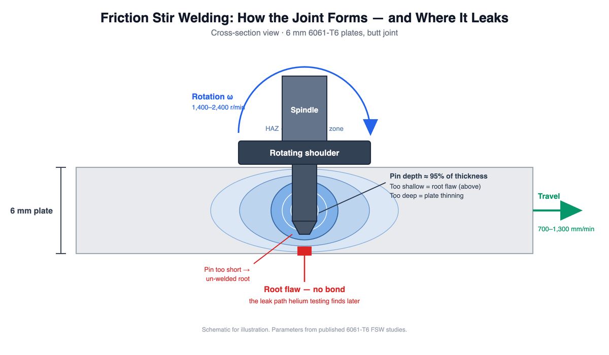
The tool looks like a stubby drill bit with a broad flat collar — the shoulder — above its threaded section, the pin. It plunges into the joint line, spins at 1,000–2,400 r/min, and is pushed along the seam. Friction and stirring heat the aluminum to roughly 400–480 °C, soft enough to knead, but short of the ~582 °C where 6061 begins to melt. The pin mixes the two faces together and the shoulder forges them flat as it passes.
The closest everyday analogy is kneading two lumps of dough together, not gluing with molten metal.
Working below the melting point removes the whole family of fusion-weld defects in one stroke:
| What you get rid of | Why it matters on a battery tray |
|---|---|
| No molten pool | No gas pores, no solidification cracks — the two defects that dominate fusion weld rejects on 6xxx alloys |
| No filler wire | Nothing to mismatch against the parent alloy, nothing for the joint to absorb moisture from |
| Much lower heat input | Far less distortion; a welded 6 mm tray stays flat enough that you usually avoid post-weld re-machining |
| No consumables | No shielding gas, no wire, no filler inventory — most of the cost per metre is machine time |
The trade is that the tool has to physically reach the joint, with something backing it from underneath. That single constraint explains nearly every limitation at the end of this article.
Inside the Weld: Three Zones
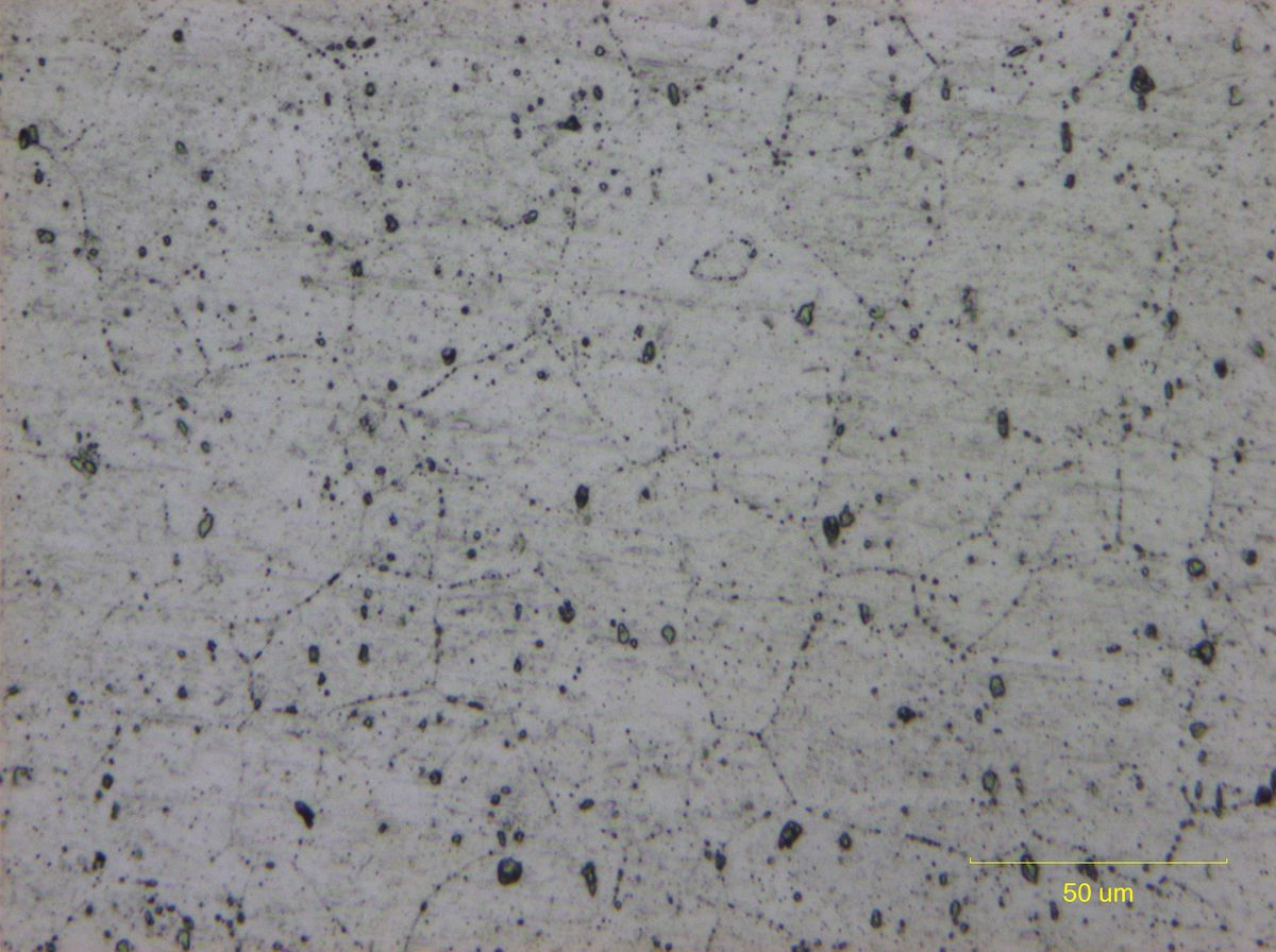
Cut any FSW joint, polish it, etch it, and three concentric bands appear. Each received a different dose of heat and deformation, and each ends up with a different structure.
| Zone | What happened to the metal | Practical meaning |
|---|---|---|
| Stir zone (the nugget) | Fully recrystallized; original grain structure replaced by fine equiaxed grains with "onion ring" bands | Fine grains make this region tough — rarely the weak link |
| TMAZ (thermo-mechanically affected) | Heated and deformed, but not recrystallized; grains bent and stretched | Transition region between nugget and parent metal |
| HAZ (heat-affected zone) | Heat only, no mechanical work | The weak link — over-aging coarsens the strengthening precipitates in a heat-treated alloy |
The last row is the one worth remembering. 6061-T6 gets its strength from finely dispersed precipitates, and the HAZ gets hot enough — with no mechanical work to restructure it — that those precipitates coarsen. No process tuning brings the hardness back.
So the strength map across a welded tray runs: parent metal, dip at the HAZ, partial recovery in the nugget. When a welded joint is pulled to failure, it breaks next to the weld, not in it.
Nugget widths on 6 mm plate run roughly 8–14 mm, tapering with depth; the HAZ spreads 5–15 mm each side. Typical figures, not a spec — the honest number comes off your own etched section.
Heat Input: The One Setting That Governs Everything
FSW has two main controls — rotation speed and travel speed — plus axial force, tool tilt (usually 2–3°) and pin geometry. Their ratio sets the heat input, and heat input decides which of three worlds you land in:
- Too little heat — the metal never plasticizes, so the pin tears through it instead of stirring. The joint looks welded and carries almost no strength.
- The right window — the metal flows like dough, the pin mixes it cleanly, and the shoulder forges a sound seam.
- Too much heat — the HAZ over-ages deeply and the seam ends up softer than the rest of the tray.
Reported figures from laboratory work and running production lines land in a narrow range:
| Setup | Rotation | Travel | Reported result |
|---|---|---|---|
| 6 mm 6061-T6 plate, laboratory optimum | 1,400 r/min | 700 mm/min | Defect-free; UTS 252.89 MPa; impact energy 2.87 × base metal |
| Super-large integral tray, dual-robot cell | 2,000–2,400 r/min | 1,000–1,300 mm/min | Axial force 5,300–6,000 N; Ø10 mm stationary shoulder, 1 mm plunge, 3.2 mm bead |
| Production line after a leak failure was corrected | 1,500 r/min | 800 mm/min | Yield stabilized at 99.8%+ |
The rotation-to-travel ratio across all three runs between 1.5 and 2.4. Production settled slower than the laboratory optimum — on a real line you trade a little joint strength for stability against clamping variation, thermal drift, and tool wear.
How Strong the Joint Is
Measured on 6 mm 6061-T6, against the minimums EN 755-2:2016 guarantees for the parent extrusion:
| Property | Parent extrusion guarantee | FSW joint (measured) | Efficiency |
|---|---|---|---|
| Ultimate tensile strength | ≥ 260 MPa | 252.89 MPa | 80.45% |
| Yield strength | ≥ 240 MPa | 172.68 MPa | ~72% |
| Average impact energy | baseline | 2.87 × baseline | 287% |
Plan on ~80% of parent tensile strength, ~72% of yield. The HAZ softening described above is exactly why the gap exists.
The impact line is the surprise: nearly three times the parent metal. The recrystallized grains in the stir zone are fine and equiaxed, and that structure absorbs energy better than wrought plate. For a tray that has to survive a bottom strike, that is a genuinely useful property.
Why Tray Welds Leak: The Un-Bonded Root
Here is the failure from the opening, reported on a batch-produced EV lower tray. Trays were leaking. Sectioning showed "cold weld" lack of bonding at the joint root, traced to severe pin offset: the pin had drifted off the joint centreline, stirring one side properly and merely rubbing the other.
The geometry explains everything. The shoulder rides on the surface and forges the top 1–2 mm — so the top always looks good. The root, 5–6 mm down, is where the pin has to reach. If the pin is offset, one side of the joint is stirred and the other is only rubbed, and the un-bonded strip becomes a continuous tunnel along the weld: a leak path that no visual inspection will find, visible only under pressure decay or helium testing.
Two corrective actions solved it:
- Laser tracking to hold pin centreline within ±0.2 mm — the decisive one.
- Process re-optimization to 1,500 r/min at 800 mm/min.
Yield stabilized at 99.8%+ after both. Pin depth is the companion risk: too shallow and the root stays un-bonded; too deep and the tip ploughs into the backing plate, thinning the tray from below and producing the same leak from the other side. The usable margin is a few tenths of a millimetre.
The pattern to take away: FSW quality is decided below the surface. The bead you can see tells you almost nothing about the root you cannot.
Where FSW Reaches Its Limits
Three boundaries matter when weighing it against one-piece die casting:
- Section depth. The tool reaches only 2–3 mm below the surface in practice. A member loaded along its length cannot be welded through its full section — there is no way to get a pin there. That is the main structural argument for casting: no weld, no leak path. Reported figures on the casting route: vacuum die casting holding porosity at 0.3%, tensile around 280 MPa, and large integral trays near 66.7 kg.
- Access and path. The joint needs backing underneath and clearance for the tool to travel. Long straight seams suit it; complex three-dimensional joint paths do not.
- Every start and stop leaves an exit hole that has to be plugged or trimmed — a small thing, but one more manufactured feature on a sealed enclosure.
None of this makes FSW weak. It makes FSW a linear, surface-reaching process — outstanding for the long seams of an extruded tray, and simply not the tool for geometry it cannot reach.
FAQ
What is friction stir welding, in one sentence? A solid-state process that joins aluminum without ever melting it — a spinning tool kneads the two faces together below the melting point instead of fusing them in a molten pool.
Is FSW better than MIG or TIG for an aluminum battery tray? For 6xxx alloys, almost always. MIG and TIG bring gas porosity, solidification cracking and thin-section distortion, and 6xxx is notoriously crack-sensitive under fusion welding. FSW avoids all three.
Can an FSW joint match the strength of the parent extrusion? No — expect about 80% of parent tensile strength (252.89 MPa measured against the 260 MPa standard minimum for 6061-T6) and around 72% of yield, because the heat-affected zone over-ages. Good design keeps welds out of primary load paths.
Why does a tray that looks perfect fail leak testing? Because the pin drifted off the joint centreline, leaving the root un-bonded a few millimetres below a good-looking surface. Visual inspection cannot see it; only pressure decay or helium testing finds it.
Does a welded tray need extra sealing beyond the weld? Yes. The weld is not the seal line at connector interfaces. High-voltage connectors and communication ports rely on their own gaskets or form-in-place seals, and in testing those fail more often than welds do.
Related Reading
- How Aluminum Extrusion Works (Battery Box Edition) — where the profiles being welded come from
- Extrusion vs Die Casting vs Stamping for Battery Housings — the process choice one level above this one
- How Battery Boxes Are Leak Tested (4 Methods Compared) — how that 3.2 × 10⁻⁶ reading was taken
- 6063 vs 6061 vs 6082: Which Aluminum Alloy for Battery Boxes — alloy selection before welding
Related guides
- How aluminum battery boxes are made — the manufacturing routes and volume thresholds
- Aluminum battery box materials — alloys, tempers and finishes compared
- Aluminum battery trays and covers — pack-level trays
RELATED NEWS

Need Aluminum Battery Enclosures?
From extrusion to CNC machining and anodizing, AOYIN delivers end-to-end manufacturing for EV battery housings.
Email:
Add:No 339-1 shangye village Gouxi Township Kecheng district Quzhou City, zhejiang province,China
Add:No 339-1 shangye village Gouxi Township Kecheng district Quzhou City, zhejiang province,China
-
-
-
-

WhatsApp