Quzhou Aoyin Metal Materials Co.,Ltd



Aluminum Battery Box Corrosion: Where It Starts First
Materials & finishes
Release time:
2026-10-16
Source


Aluminum battery box corrosion starts at the joints, not the open panels. Those joints are the fastener holes, the lid seal, and any seam that stays damp after the rest of the shell has dried. Every one of those places holds electrolyte against aluminum that would otherwise dry between showers.
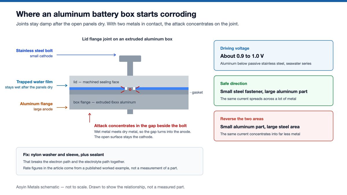
A box pulled off an e-rickshaw after two monsoon seasons usually looks sound along its side panels. Turn it over and the damage sits on the lid flange. White powder haloes each bolt head, dark pitting follows the gasket line, and the metal between them stays clean. The joints went first because the joints stayed wet.
Aluminum battery box corrosion removes wall thickness, not surface finish
Corrosion takes away a fixed depth of metal each year, so wall thickness sets how long a part lasts, and a thin wall reaches perforation first. The attack does not slow down to suit a thin section.
Aluminum is not rust-proof. It grows an aluminum oxide film within minutes of exposure, and that film keeps the metal passive. Chloride from sea air, road splash or spilled electrolyte breaks through it at weak points, and the metal underneath starts dissolving.
A fixed depth of attack takes a larger share of a thin wall. A 0.1 mm depth of attack consumes 8% of a 1.2 mm wall and 4% of a 2.5 mm wall. Both boxes still look intact. Only the thinner one is close to a hole.
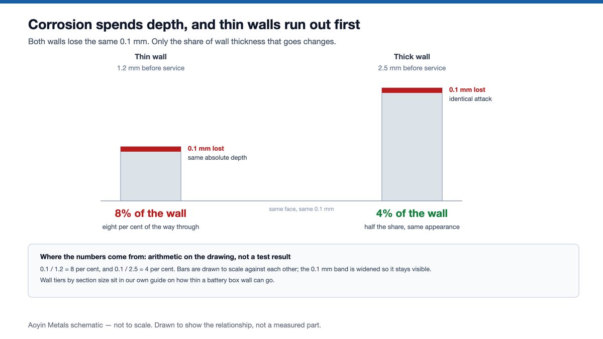
Wall thickness tiers are normally chosen for stiffness. Corrosion adds a second criterion. On a coastal or monsoon route, pick the thicker end of the range the section allows, because every micrometer of wall adds years of service.
Sheltered faces also corrode faster than washed ones. Long-term exposure work reports damp deposits held against sheltered faces, while a box under a seat never gets washed by rain.
A stainless steel bolt makes nearby aluminum the anode
In the seawater galvanic series, aluminum sits roughly 0.9–1.0 V below passive stainless steel. So once the two touch under a conducting film, the aluminum dissolves and the stainless steel does not. Electrons run to the steel, and aluminum leaves the metal as ions. No standard publishes that series; the ranking rests on measurement.
A common rule of thumb treats any pair under 0.25 V as acceptable. The aluminum–stainless pair is roughly four times that, and the area ratio below overrides the rule.
Take a published worked example. At a galvanic current density of 5×10⁻³ A/m² in a marine thin film, Faraday's law gives about 5.5 µm/yr of average penetration. Local rates commonly run five to ten times the surface average, and in that same example roughly 50 µm/yr at the fastener interface.
So a 2 mm flange thins visibly at its worst point over decades of exposure. Perforation arrives first where the wall is thinnest. The galvanic couple and the water set how deep that attack goes, and panel thickness plays no part in it.
The anode-to-cathode area ratio sets how concentrated the attack becomes
Keep aluminum as the large part and stainless steel as the small fastener, then break the circuit. Swapping those two areas turns a mild pair into a perforated flange. The corrosion current stays the same either way. What changes is the aluminum area that current lands on.
A small anode feeding a large cathode has nowhere to spread the current, so the small anode dissolves fast and locally. A large anode feeding a small cathode spreads the same current across itself and thins very little. One couple, two drawings, opposite outcomes.
Sealing design runs on the same logic. Water held in a joint instead of shed from it builds the same cell that later shows up as a failed leak test.
| What varies | Effect on the rate | What changes it |
|---|---|---|
| Potential difference | aluminum against stainless runs roughly 0.9–1.0 V apart | pick plating or aluminum fasteners instead, and the difference collapses |
| Area ratio | small anode against large cathode concentrates the current | aluminum stays the big part, steel stays the small fastener |
| Wet time | a joint that never dries corrodes all year | drain holes, shed geometry, and joint compounds that exclude water |
| Chloride level | higher conductivity lets the cell drive harder | rinse regimes and siting away from salt spray |
| Anodic film | typically 5–25 µm for Type II, ≥25 µm for Type III | thicker film buys time; it does not stop the couple |
| pH of the film | oxide holds roughly pH 4–8.5 | avoid alkaline degreasers and acidic spills on the same part |
| Wall thickness | 0.1 mm costs 8% of 1.2 mm and 4% of 2.5 mm | thicker wall on thin, always-wet sections |
> The values in this table are typical figures and working rules drawn from industry practice and published exposure work. Only the wall thickness row is arithmetic. None of them are minimum values set by a standard.
Salt spray sets the conditions; the drawing sets the pass mark
ASTM B117 fixes how the chamber runs: 5% sodium chloride and collected solution at pH 6.5–7.2. The cabinet sits at 35 °C ± 2 °C, and settling runs 1–2 mL per 80 cm² per hour. It fixes no acceptance limit at all. Put the hour count and the acceptance appearance on the drawing.
GB/T 10125 and ISO 9227 describe the same neutral spray conditions, so a cabinet qualified to one of the three is running the same exposure. Accelerated variants exist: acetic salt spray runs at pH 3.1–3.3, and the copper-accelerated version adds copper chloride at 50 °C ± 2 °C for a harder drive.
Anodized parts are commonly qualified over 96 h and 336 h. No standard sets those two periods; they are trade practice.
Reading the panels taken out of the chamber gives the most information. Corrosion area percentage comes from a grid or image analysis. Pit density and maximum pit depth come off a metallographic cross-section, and mass loss converts to a rate in mm/yr. Blister size and density are rated on coated parts.
Why aluminum battery box corrosion starts in the joints
Four causes account for most battery box failures: trapped geometry, film damage, machining residue, and metallurgy. Three of the four keep electrolyte against aluminum that would otherwise dry between wet periods.
Geometry that traps water comes first. In a saltwater test on die-cast ADC12 aluminum against a rubber O-ring, the sealing face corroded deeper than the exposed face (SAE 2014-01-0997). That alloy is a die-casting composition with lower corrosion resistance than extruded 6xxx material, so its depth figures do not transfer. The mechanism does transfer: trapped electrolyte and oxygen depletion at the interface.
Oxygen depletion explains the rest of the mechanism. Oxygen in a narrow gap falls as the metal consumes it. The gap becomes the anode while the open surface acts as the cathode. Current concentrates there, out of reach of any visual check.
Drying time explains why fastener holes go first. Moisture in seams, under bolt heads and in blind holes stays there long after the open metal dries. On a vehicle working through a monsoon, that difference in drying time explains most of the damage.
Film damage and machining residue are the next two. A film below its specified thickness, a pinhole, or a handling scratch leaves bare metal at that one spot. Machining contributes twice: chloride-bearing cutting fluid stays behind as a corrosion source, and a burr on a mating face creates the gap. Schedule deburring and a chloride-free rinse as inspection steps, alongside the finish notes.
Metallurgy is the fourth, and no amount of draining fixes that cause. Higher magnesium content, or excess iron and silicon, raises pitting susceptibility. Material selection settles that before any metal gets cut. Intergranular attack follows a sensitized grain structure left by heat treatment, and shows up at welds on enclosures that are welded.
That same saltwater study also found that smoother sealing faces and narrower, well-compressed gaps measurably slowed the attack. Better finish and tighter compression slow the attack; they do not remove it. Put both on the drawing as machining tolerances, alongside the finish note.
An anodic film delays the attack and does not grow back
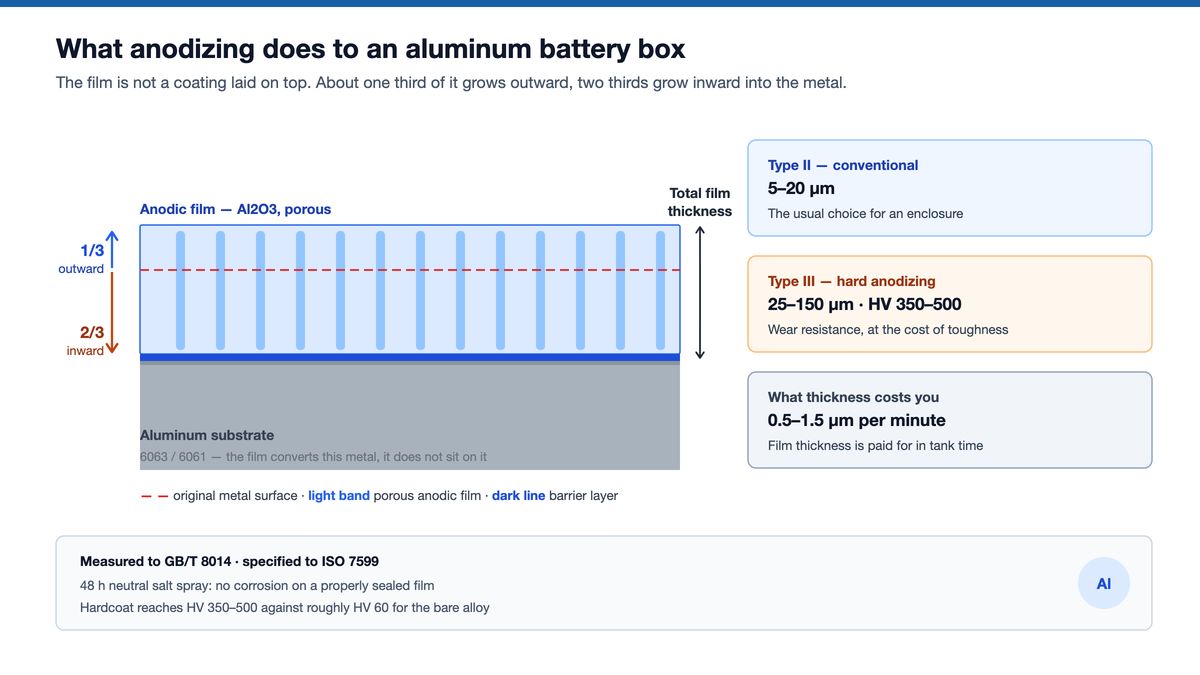
An anodic film delays the attack but cannot renew itself. Once the layer is cut through it does not regrow, and bare aluminum only rebuilds a nanometer-scale natural oxide. Stainless steel re-forms its passive film in seconds. Anodized aluminum has no equivalent.
Thickness runs in tiers. Type II typically measures 5–25 µm. Type III is defined at 25 µm and above, and commercial hard anodizing commonly runs 25–50 µm. One common industry specification for electric-vehicle enclosures is Type II at 15–20 µm on 6061-T6.
In long-term industrial-atmosphere exposure work, only films beyond about 25 µm stayed free of pitting across ten years.
The film also has a working pH window, though no standard governs the range. The window runs roughly from pH 4 to 8.5, and both strongly acidic solution below about pH 3–4 and alkaline solution above about pH 9 dissolve the oxide outright. Spilled electrolyte and aggressive alkaline degreasers sit outside that window.
Sealing gets overlooked more often than thickness, and poor sealing shows up early as blotching, discoloration and reduced barrier performance. Machining order matters too. Roughly one-third of a Type II film grows outward, and for Type III about half of the film grows outward. The sealing face moves outward by that share unless the allowance was built into the drawing before machining.
Our own anodizing line runs both Type II and hard anodizing within one integrated production network. Film thickness is measured on every batch, and every stage is open to customer audit.
Frequently asked questions
Does aluminum battery box corrosion look like rust on steel? Aluminum corrodes to a white or gray powdery deposit with pits underneath it, not the red flaky oxide that steel sheds. That missing red color is exactly why early attack gets walked past on a routine check.
How long does an anodized battery box last in service? Salt spray hours cannot be converted into a service life. Testing bodies state that chamber results correlate with real exposure, but not in a simple linear way. So 1,000 h in the cabinet does not mean ten years on the road.
Estimate from a depth budget instead: divide the available wall thickness by the local penetration rate for that environment.
Can stainless steel bolts be used on an aluminum box? They can, provided the circuit is broken. A nylon washer and sleeve with sealant around the joint remove the electron path and the electrolyte path together. Area ratio is on the safe side here, since the stainless steel is the small cathode against a large aluminum part.
How many salt spray hours should a drawing specify? The drawing has to state them, because ASTM B117 states no pass mark: it governs cabinet conditions only. Anodized aluminum is commonly qualified at 96 h or 336 h. Write the acceptance appearance beside the hours, whether that is pit count, corroded area percentage or maximum pit depth.
Where should the first check look on a used box? Start at the sealing interface, then at fastener holes and blind holes: in one saltwater test the sealed face corroded deeper than the open face. Judge those three locations before judging the panels, and check returned parts for burrs and cutting-fluid residue. Send the drawing or the failed sample to
Related guides
- How aluminum battery boxes are made — extrusion, CNC and finishing
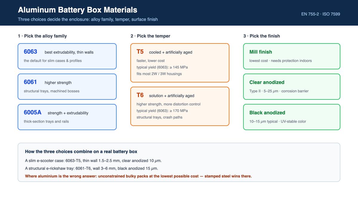
- Aluminum battery box materials — why 6063 and 6061 differ in the die and in the field
- IP54 vs IP65 vs IP67 — keeping water out before corrosion becomes the question
Diagrams: Aoyin Metals schematic, drawn to show where corrosion starts, not a measured part. Salt spray conditions from ASTM B117, GB/T 10125 and ISO 9227. Sealing-face result from SAE 2014-01-0997, observed on die-cast ADC12 instead of extruded 6xxx. Galvanic rates are a published worked calculation.
Need Aluminum Battery Enclosures?
From extrusion to CNC machining and anodizing, AOYIN delivers end-to-end manufacturing for EV battery housings.
Mobile Phone
Email:
Add:No 339-1 shangye village Gouxi Township Kecheng district Quzhou City, zhejiang province,China
Add:No 339-1 shangye village Gouxi Township Kecheng district Quzhou City, zhejiang province,China

WhatsApp