Quzhou Aoyin Metal Materials Co.,Ltd


How an Extrusion Die Shapes a Battery Box Profile
Blog
Release time:
2026-10-13
Source


The first length comes off the press bent
An extrusion die sets the shape of a profile and the speed at which every part of that shape leaves the steel. Get the speeds uneven and the section bends, however good the billet was.
The first length comes out of the press and it is not straight. Six meters of box section bows to one side, then twists as it cools on the runout table. The billet was in spec. The operator changed no setting. The die is brand new. When one wall exits faster than the wall beside it, the length bends toward the slow side. Most first-article problems trace back to it.
What a die is, and what it decides
An extrusion die is a block of hot-work tool steel with an opening cut through it, and that opening is the cross-section you receive. A billet enters one side at roughly 480–520°C and your profile leaves the other at that same shape for as long as the die lasts.
Think of a piping nozzle on a cake. The opening sets the shape of the icing; the channel behind it sets the speed. An aluminium extrusion die runs on the same two variables: the opening gives the section its geometry, and a short straight channel behind it, the bearing, sets how fast each part of that geometry exits.
Hollow sections add a step: a solid billet has no hole, yet a box section does.
How metal moves through an aluminium extrusion die
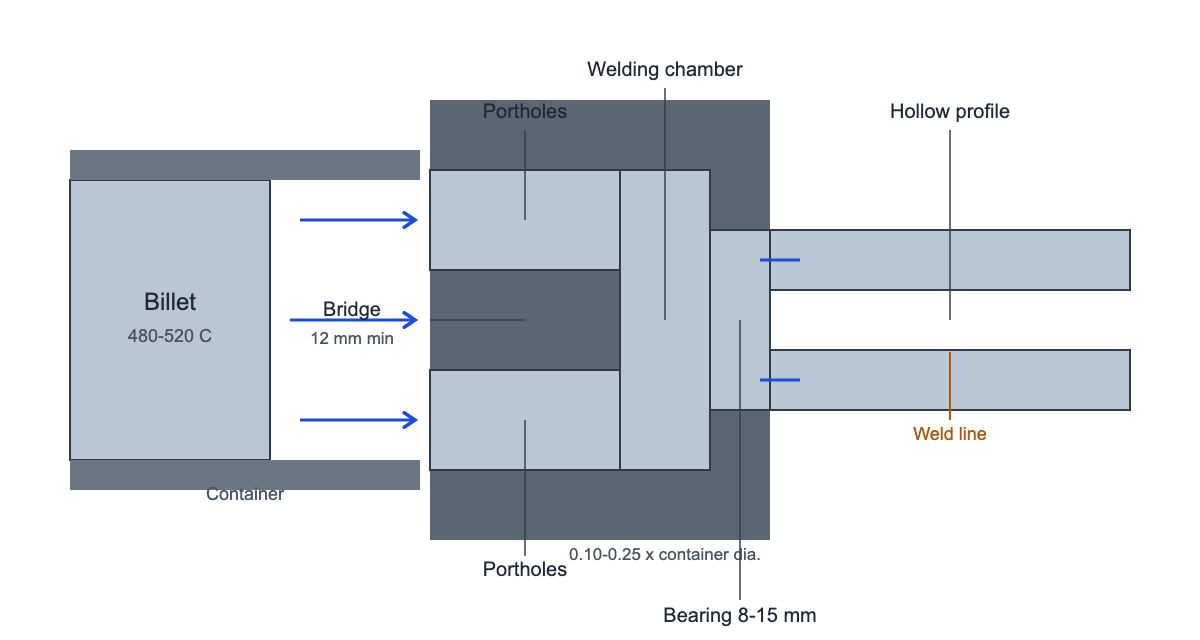
In a porthole die the billet splits into several streams around steel bridges, and those streams rejoin under pressure in a welding chamber before they reach the bearing. No hole is pierced first. The bridges cut the flow apart; the chamber pushes it back together.
That rejoining leaves a weld line running the length of the profile, one per bridge. Whether it holds depends on pressure and temperature inside the chamber, not on anything an inspector can see later. A seam that survives sealing and leak testing was bonded; one that shows as a dark line after anodizing was not.
Downstream sits the bearing, the last few millimeters of straight steel the metal touches.
Why die bearing length controls flow speed
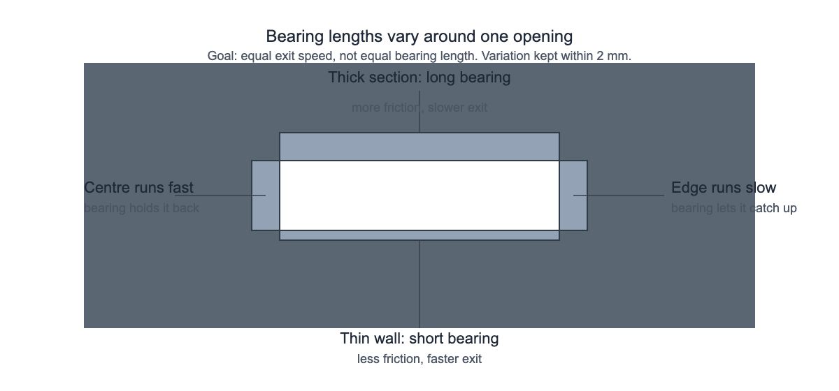
A longer bearing adds friction, so metal leaves that part of the opening more slowly; die designers use it as a local brake to even out exit speed. Metal does not arrive at the die face at one uniform speed. Friction against the container wall slows the metal near the billet surface, so the center runs ahead of the edge. Thin legs flow slower than thick sections, because the opening is smaller.
The correction is deliberately uneven: fast areas get a longer bearing to hold them back, slow areas a shorter one to let them catch up. The target is uniform exit velocity around the whole perimeter, not uniform bearing length. A die with every bearing cut to the same length is a die that has not been balanced.
The numbers set into an aluminium extrusion die
These are the thresholds a die shop checks before it cuts steel. They are shop practice, not standard values, and they move with alloy and press size.
| Item | Typical value | What happens outside it |
|---|---|---|
| Design wall thickness | ≥1.2 mm for production; 6063 can reach 0.5 mm in theory | Below about 1.2 mm the die teeth are too fragile for a run |
| Extrusion ratio, 6063 | 15–30 | Above roughly 60, press load climbs fast |
| Extrusion ratio, 6061 | 10–25 | 6061 resists deformation more than 6063 |
| Split ratio K, hollow dies | 6063: 15–30; 6061: 20–40 | K below 10 gives thin walls and incomplete welds |
| Combined check | K × extrusion ratio = 45–200 | Outside that band, flow is hard to balance |
| Bearing length | 8–15 mm | Shorter wears out fast; longer caps press speed |
| Bearing variation across the die | ≤2 mm | Every 1 mm of difference shifts local speed by about 10% |
| Minimum die thickness | 0.12 × container diameter + 15 mm | Thinner dies deflect when hot and push dimensions up 0.1–0.3 mm |
| Bridge width | ≥12 mm | Narrower bridges crack under load |
| Welding chamber depth | 0.10–0.25 × container diameter | Too shallow welds poorly; too deep traps oxide and leaves dark lines |
| Shrinkage allowance | 6063: 0.8–1.0%; 6061: 1.0–1.2% | The die opening is cut larger to land on the nominal size |
Two of these carry most of the weight: bearing variation sets whether the section comes out straight, chamber depth whether the weld line holds.
What the section measures when the die is right
On a 6063-T6 section up to 10 mm thick, GB/T 6892-2018 sets minimum mechanical properties at 205 MPa tensile and 180 MPa yield, with the ordinary dimensional class applying unless the order names high precision. At T5 the same standard lists 160 MPa tensile and 110 MPa yield.
Dimensional bands follow the class named on the order. On a 2 mm wall, the ordinary class allows ±0.23 mm and high precision allows ±0.15 mm. Both parts pass inspection. That gap is why wall thickness and tolerance class belong on the drawing, not in a phone call. Aluminium battery box materials covers why 6063 and 6061 behave differently in a die.
Die steel runs at HRC 48–52 in H13, and bearing lands finish at Ra 0.8 μm or better.
Why a good die still produces bad sections
Four failure modes account for most rejected first articles, and each one has a number behind it.
Sections twist or bow when bearing variation exceeds 2 mm. At roughly 10% speed difference per millimeter, a 3 mm spread across the die is enough to pull a six-meter length off line. The fix is die correction, not a press setting.
Weld lines open up when the split ratio drops below 10 or the chamber is too shallow; the streams meet without enough pressure to bond. A chamber cut too deep does the same thing by another route, because metal sits in it long enough to grow oxide that travels into the weld.
Dimensions drift up by 0.1–0.3 mm when the die is thinner than 0.12 × container diameter + 15 mm. It deflects under load at temperature, so every part in the run comes out large and consistent, which looks like a tolerance problem, not a tooling one.
Bridges crack when they are cut narrower than 12 mm, which ends the tool early. Underneath all four sits the same variable: how the press and die share the work at temperature.
Where the die reaches its limits
An extrusion die fixes the cross-section; what it cannot fix is an abrupt wall change, a deep unsupported tongue, or a dimension revised after the tool is cut.
Wall thickness cannot change abruptly. A step above about 30% between adjacent walls leaves thick sections feeding thin ones unevenly, and the thick part sinks or goes porous.
Semi-hollow features top out at about 3:1 depth to width. A tongue in the middle of the section reaches 8:1, supported from both sides; an unsupported leg at the edge cannot.
A die fixes the section. Changing one dimension after the tool is cut usually means a new die or a rework, and either one adds weeks before a first article can be measured. That is why the eight dimensions fixed before a drawing are worth settling in that order.
FAQ
What is a die bearing? The last straight channel before the metal leaves the die, typically 8–15 mm long. Its length at each point sets how fast metal exits there.
Why does my profile twist? One part of the cross-section is leaving faster than another. The usual cause is bearing variation above 2 mm across the die.
Is a weld line a defect? Not by itself; every hollow profile has one per bridge. It becomes one when the streams do not bond, showing as a dark line after anodizing or a leak path under pressure.
Can any cross-section be extruded? No. Wall steps above about 30% and unsupported tongues deeper than about 3 times their width are outside what a die holds.
How long does a die last? The bearing sets it. It is the only part in sliding contact with hot aluminium, so it is the part that wears.
Send the section you are still drawing to info@aymetals.com, or reach us on WhatsApp at +86 133 0570 9557.
Request a Quote
Need a custom aluminum battery box for e-rickshaw or 3-wheeler EV? Send us your drawing or specs and we will reply within 24 hours.
WhatsApp UsEmail info@aymetals.com
WhatsApp: +86 133 0570 9557 | Email: info@aymetals.com
Related: How aluminium extrusion works | Battery box wall thickness: how thin is too thin
Related guides
How aluminium extrusion works — the press and billet side of the process
Battery box wall thickness: how thin is too thin — where the 1.2 mm floor comes from
Aluminium battery box materials — why 6063 and 6061 behave differently in a die
Custom OEM solutions — from drawing to a finished enclosure
Diagram: Aoyin Metals schematics. Mechanical properties cite GB/T 6892-2018 for 6063. Die thresholds are shop practice, not standard values.
RELATED NEWS

Need Aluminum Battery Enclosures?
From extrusion to CNC machining and anodizing, AOYIN delivers end-to-end manufacturing for EV battery housings.
Mobile Phone
Email:
Add:No 339-1 shangye village Gouxi Township Kecheng district Quzhou City, zhejiang province,China
Add:No 339-1 shangye village Gouxi Township Kecheng district Quzhou City, zhejiang province,China

WhatsApp